
 Tweet
Tweet
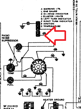
Guys can anyone tell me what the TSM is refering to here?
The connector I have a red arrow on, is that supposed to be the
circle / ring instrument cluster connector?
If so what pin ?
I have 3 gauges out, TSM suggests that my temp gauge w/ CVR is bad
but what about this part?
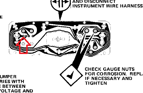
The connector I have a red arrow on, is that supposed to be the
circle / ring instrument cluster connector?
If so what pin ?
I have 3 gauges out, TSM suggests that my temp gauge w/ CVR is bad
but what about this part?


Comment