

 Tweet
Tweet
Play nice everyone.
Now back to your regularly scheduled programming.
Now back to your regularly scheduled programming.
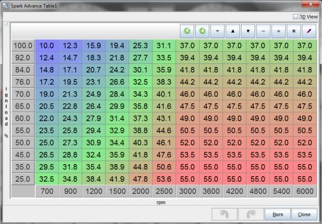
 , fired it up on Sunday after finishing up all the wiring. So far so good, had it running for a few hours in the driveway checking everything out, just need to get out and do some tuning now. I went ahead and removed all the factory ignition system while I was making the wiring harness and let MS control the ignition as well.
 It's very drivable as it is now, I really need to focus on getting the cage done.
 Will post up some pics when I get a chance.


Comment