Megasquirt2 Install AMC360 TBI 83' Cherokee

Collapse
This is a sticky topic.
X
X
 
  • Filter
  • Time
  • Show
Clear All
new posts
  • myk
    232 I6
    • Jan 30, 2011
    • 82

    #16
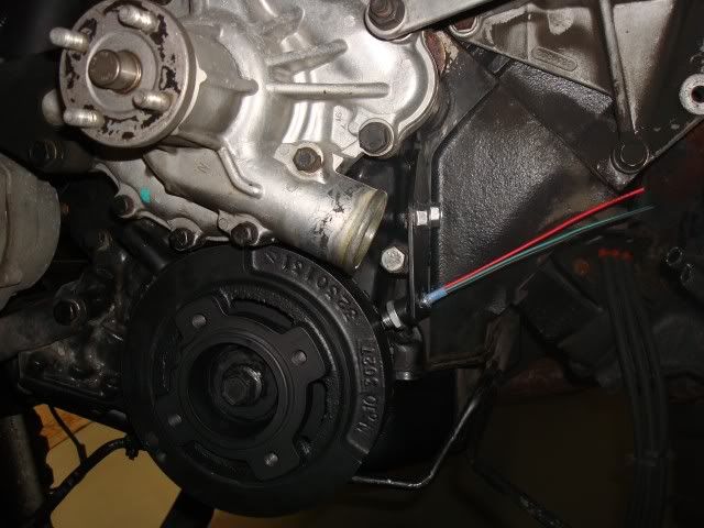
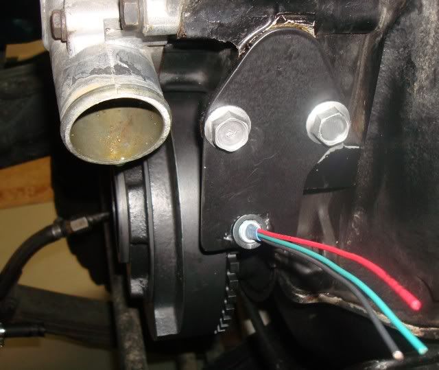
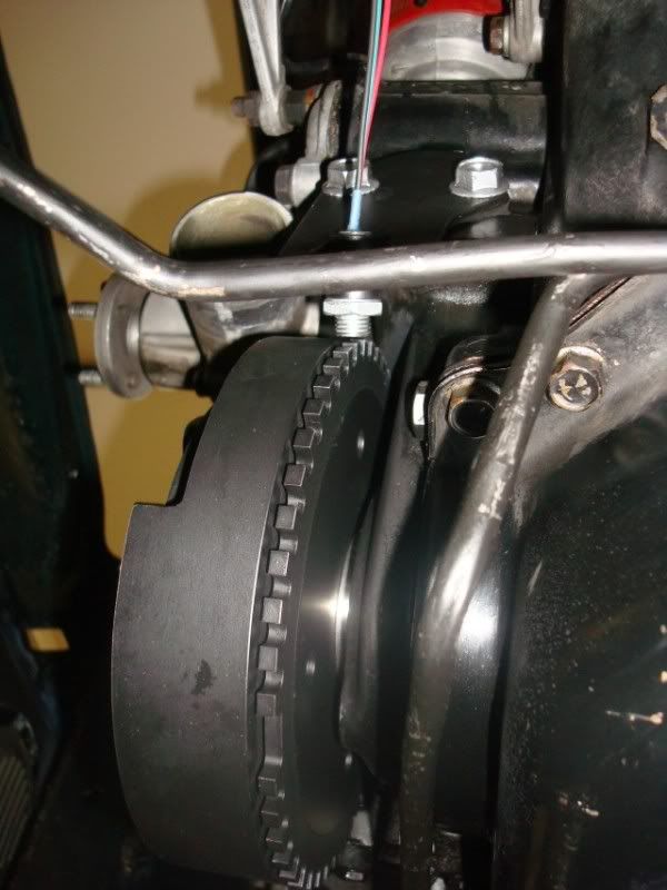
    Here are the pictures of the completed toothed wheel install and the bracket to mount the gear tooth hall sensor. I fabbed up the sensor from an Allegro 616 and potted it into a threaded stud with a locknut, the bracket also serves as the fuel pump blockoff plate, I just extended it a few inches and welded a threaded bung to it at the proper angle for the wheel.

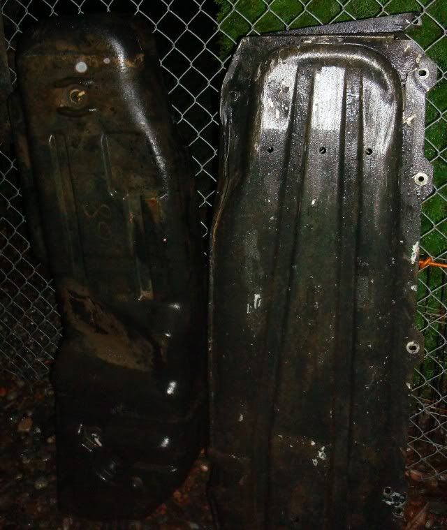
    Next up is the gas tank....

    Mike


    Comment

    • myk
      232 I6
      • Jan 30, 2011
      • 82

      #17
      Gas tank is out, can only hope I never have to do that again in my life. There must have been twenty pounds of dirt and rocks crammed in that shield around the tank. When I rebuilt the rig 10+ years ago that's the only thing I never removed under the rig so there was plenty of old crap in there, even found part of an old u-joint that expoded at some point in time


      Here's the part I need to modify, planning on adding a 3/8" pickup and return. Haven't completely figured out the best way to do it yet but probably silver solder in some new lines in the existing flange. Need to figure out if I can remove the fuel gauge sending unit while I'm doing it so it doesn't get ruined from the heat. I think I'll ditch the screen filter and just run the pickup tube down to the bottom of the tank and use an external pre-pump filter and also a post-pump filter both easy to get to on the frame rail. The return line will also run down near the bottom of the tank.


      Here's the fuel pump a Walbro GSL392 and the AEM 0-100psi fuel pressure sensor, this lets me log the fuel pressure in the Megasquirt ECU. Also got the wiring harness material and an IGN-1 coil from diyautotune. Getting closer, I'll be glad when the tank's back in, I knew it would be the toughest part of the whole deal.


      Comment

      • tgreese
        • May 29, 2003
        • 11682

        #18
        Some questions about your choices of components, if I may.

        The tooth wheel seems like a lot of extra complexity when you already have a spark signal from the Motorcraft distributor. You could follow the 7-pin approach described here http://www.megamanual.com/ms2/GM_7pinHEI.htm or even use the on-board single coil spark provision on the 3.0 board.

        What advantage does the Walbro pump have over, say, the Airtex E200 http://www.rockauto.com/catalog/moreinfo.php?pk=59606 and is somewhat cheaper?

        I presume you will mount the Walbro pump lower than the lowest tank level, to avoid loss of pump prime?
        Tim Reese
        Maine beekeeper's truck: '77 J10 LWB, 258/T15/D20/3.54 bone stock, low options (delete radio), PS, hubcaps.
        Browless and proud: '82 J20 360/T18/NP208/3.73, Destination ATs, 7600 GVWR
        Copper Polly: '75 CJ-6, 304/T15, PS, BFG KM2s, soft top
        GTI without the badges: '95 VW Golf Sport 2000cc 2D
        ECO Green: '15 FCA Jeep Cherokee KL Trailhawk

        Comment

        • chrism
          327 Rambler
          • Apr 07, 2002
          • 634

          #19
          What type of signal does that fuel pressure sensor put out?
          1979 Cherokee
          1979 CJ-7

          Comment

          • myk
            232 I6
            • Jan 30, 2011
            • 82

            #20
            Originally posted by tgreese
            Some questions about your choices of components, if I may.

            The tooth wheel seems like a lot of extra complexity when you already have a spark signal from the Motorcraft distributor. You could follow the 7-pin approach described here http://www.megamanual.com/ms2/GM_7pinHEI.htm or even use the on-board single coil spark provision on the 3.0 board.
            It's all about accuracy, the ECU uses a prediction algorithm to determine when to fire the coils based on feedback from the RPM sensor. The more teeth you have the better it can determine when to do this. With the cam moving half the speed as the crank and the motorcraft dizzy only having 8 vanes, the crank wheel setup I have gives the ECU 12 times as much data per cycle to predict the spark which leads to greater timing accuracy. Also with taking the RPM signal from the distributor you introduce all the slop of the crank to cam gears/chain as well as the cam to distributor gears, the timing will also start to drift over time as the cam chain wears. So yes it is was a bit more work but well worth the benefits imho, if you were to go look at any newer car/truck you would be hard pressed to find one without a crank trigger setup for all these reasons.

            Originally posted by tgreese
            What advantage does the Walbro pump have over, say, the Airtex E200 http://www.rockauto.com/catalog/moreinfo.php?pk=59606 and is somewhat cheaper?

            I presume you will mount the Walbro pump lower than the lowest tank level, to avoid loss of pump prime?
            I'm not familiar with the Airtex pump, however the Walbro pump is a very proven pump and will support future growth if I need it (higher HP, MPFI, etc.) the price seemed reasonable, I got it for ~100 with the mounts and end fittings.

            I will mount it in the frame rail as low as possible and as close to the tank as possible. That's about the only option I can see that I have.

            Mike
            Last edited by myk; 03-30-2011, 10:40 AM.

            Comment

            • myk
              232 I6
              • Jan 30, 2011
              • 82

              #21
              Originally posted by chrism
              What type of signal does that fuel pressure sensor put out?
              It's a linear 0.5-4.5v output, below is a link to the sensor specs

              Let AEM help you win big with accessories, sensors, and connectors for your next race. Shop our site to find essential tools like pressure and map sensors!

              Comment

              • tgreese
                • May 29, 2003
                • 11682

                #22
                Mike, thanks for the detailed reply.

                Originally posted by myk
                ...
                I will mount it in the frame rail as low as possible and as close to the tank as possible. That's about the only option I can see that I have.
                I wondered about this issue. I've done a little armchair TBI-ing and it seems the alternatives are either an in-tank high-pressure pump, or a second low-pressure pump that fills a surge tank, before the external high-pressure pump. Then your high-pressure pump can be placed at any location below the surge tank, even in the engine compartment.

                Making a surge tank with a spin-on fuel filter looks straightforward, ala http://www.midnightdsigns.com/james/FuelSystem.htm

                Tim Reese
                Maine beekeeper's truck: '77 J10 LWB, 258/T15/D20/3.54 bone stock, low options (delete radio), PS, hubcaps.
                Browless and proud: '82 J20 360/T18/NP208/3.73, Destination ATs, 7600 GVWR
                Copper Polly: '75 CJ-6, 304/T15, PS, BFG KM2s, soft top
                GTI without the badges: '95 VW Golf Sport 2000cc 2D
                ECO Green: '15 FCA Jeep Cherokee KL Trailhawk

                Comment

                • tgreese
                  • May 29, 2003
                  • 11682

                  #23
                  Originally posted by myk
                  ...

                  I'm planning on using a 36-1 toothed wheel on the crank pulley for the tach signal plus a one tooth sensor in the distributor both using Allegro gear tooth sensors (had great experience with this setup on past installs)

                  ...
                  Mike, I'd like a little more about the one tooth sensor in the distributor, if you've gotten that far. Why do you need a cam sensor? You already have the crank sensor, which you could divide by 2 (big gap) or 72 (small gaps) to get the one tooth input from the distributor.

                  I presume you can make this from a Motorcraft distributor by grinding away seven of the reluctor tabs. You could even use the existing VR trigger, though you said you wanted to fit a Hall effect trigger.

                  I found some discussion of capability in the MSExtra docs, but no explanation of reasoning. I expect you have thought about the issues, and I would be interested in your reasoning.
                  Tim Reese
                  Maine beekeeper's truck: '77 J10 LWB, 258/T15/D20/3.54 bone stock, low options (delete radio), PS, hubcaps.
                  Browless and proud: '82 J20 360/T18/NP208/3.73, Destination ATs, 7600 GVWR
                  Copper Polly: '75 CJ-6, 304/T15, PS, BFG KM2s, soft top
                  GTI without the badges: '95 VW Golf Sport 2000cc 2D
                  ECO Green: '15 FCA Jeep Cherokee KL Trailhawk

                  Comment

                  • myk
                    232 I6
                    • Jan 30, 2011
                    • 82

                    #24
                    I've seen that type of setup before and was always curious why the low pressure pump wouldn't encounter the same issues that the high pressure pump would? maybe the design is better suited to pull fuel?

                    If I mount the pump on the frame as low as possible it should be right at the same level as the bottom of the tank, this would seem to be the equivalent of an in-tank pump, the only difference being the longer run of hose to the pick-up which could be a substantial issue?

                    I'll try it out and see how it behaves, I have the fuel pressure sensor so It will be easy to see any issues. Thanks for the diagram that could be a good back-up plan if I have issues when the tank is low.

                    Mike

                    Comment

                    • myk
                      232 I6
                      • Jan 30, 2011
                      • 82

                      #25
                      Originally posted by tgreese
                      Mike, I'd like a little more about the one tooth sensor in the distributor, if you've gotten that far. Why do you need a cam sensor? You already have the crank sensor, which you could divide by 2 (big gap) or 72 (small gaps) to get the one tooth input from the distributor.

                      I presume you can make this from a Motorcraft distributor by grinding away seven of the reluctor tabs. You could even use the existing VR trigger, though you said you wanted to fit a Hall effect trigger.

                      I found some discussion of capability in the MSExtra docs, but no explanation of reasoning. I expect you have thought about the issues, and I would be interested in your reasoning.
                      For the current TBI install your right, I do not need the cam sensor as it is non-sequential fueling and still uses the dizzy to distribute the sparks. I was thinking ahead if I switch to sequential MPFI and/or COP in the future I would already have the hardware and wiring setup for it. The sequential code needs to know engine cycle phase which it cannot get from the crank sensor alone i.e. it cannot tell between TDC compression and TDC exhaust with only the crank sensor.

                      That's exactly what I planned with the dizzy was cutting all but one of the vanes away and replacing the VR with a hall sensor (they just work better imho). The code only uses the cam signal for phase info and uses the crank trigger for the actual precision timing so the cam sensor accuracy is not very important just needs to know if its on compression or exhaust.

                      Mike

                      Comment

                      • tgreese
                        • May 29, 2003
                        • 11682

                        #26
                        Originally posted by myk
                        I've seen that type of setup before and was always curious why the low pressure pump wouldn't encounter the same issues that the high pressure pump would? maybe the design is better suited to pull fuel?
                        I don't know - but I do know that lots of people have used the low pressure electric fuel pumps with carburetors, and I don't recall any worries about mounting the pump low. The usual advice is "as close to the tank as possible."

                        One approach I've been mulling over: use the original mechanical pump to fill the accumulator. This would retain all of the factory fuel plumbing aft of the engine compartment. Certainly the mechanical pump is capable of drawing fuel from the tank, rather than pushing it to the front of the car. The accumulator approach would also radically shorten the length of the high pressure circuit, which I believe would be a net plus, both in terms of simplicity and peak pressure / fuel delivery rate.

                        If I mount the pump on the frame as low as possible it should be right at the same level as the bottom of the tank, this would seem to be the equivalent of an in-tank pump, the only difference being the longer run of hose to the pick-up which could be a substantial issue?
                        I would think so, except for the additional drag with the longer inlet path. This is equivalent to a pressure differential across the input path that the pump must overcome. By mounting the pump higher or lower, you are changing the gravity term in that equation. Mount the pump low enough, and the weight of the fuel column overcomes the drag, and fuel comes out the inlet without pumping. The hydrodynamic (petrodynamic?) drag doesn't change with the mounting height - instead the drag depends on the path length, curvature, and pipe diameter. So if your combination of these factors doesn't starve the pump, it'll work.

                        Probably overly analytical, but maybe of interest.
                        Last edited by tgreese; 03-31-2011, 06:21 AM.
                        Tim Reese
                        Maine beekeeper's truck: '77 J10 LWB, 258/T15/D20/3.54 bone stock, low options (delete radio), PS, hubcaps.
                        Browless and proud: '82 J20 360/T18/NP208/3.73, Destination ATs, 7600 GVWR
                        Copper Polly: '75 CJ-6, 304/T15, PS, BFG KM2s, soft top
                        GTI without the badges: '95 VW Golf Sport 2000cc 2D
                        ECO Green: '15 FCA Jeep Cherokee KL Trailhawk

                        Comment

                        • chrism
                          327 Rambler
                          • Apr 07, 2002
                          • 634

                          #27
                          On your fuel system. I took the sending unit that looks similar to your pics.
                          Cut the bottom portion of the tube off and clamp some vice grips to the top portion. Heat the tube from the top with a torch and the existing solder will melt. You should be able to pull the tubes right out. Re-drill to the proper size make your new tubes and solder them back in.

                          What we found that works well (especially in the coffin shaped tanks) is using two or more of these pickups in the bottom of the tank. They will get your pickup right down to the bottom of the tank and provide some filtering.
                          High performance Walbro fuel pump sales and more by Auto Performance Engineering. Since 1997, APE has been THE place to find a Walbro fuel pump!


                          Your Walbro pump is the equivalent of the Airtex E8248 which is the higher performance version of the E2000. I have heard good things about the Walbro pumps. I use the E8248 mounted on the frame rail with the walbro pickups to feed my LT1 and it works well. The problem I had before I added the pickups was that when I got down to less than 1/2 tank and hit the brakes the fuel would head to the front of the tank and starve the pump (the sock on the stock pickup was also shot which made this even worse). So now I have two pickups. One directly to the bottom of the tank from the sender and one that extends up towards the front of the tank. No more starvation issues.

                          This summer I plan on replacing the stock tank completly with a rear mounted S10 blazer tank that has an in tank setup with the proper EFI baffles inside the tank. I am hoping that in addition to a better fuel delivery system it will also help with the buildup of junk that tends to rot out the driver side frame rail .
                          1979 Cherokee
                          1979 CJ-7

                          Comment

                          • myk
                            232 I6
                            • Jan 30, 2011
                            • 82

                            #28
                            Originally posted by chrism
                            On your fuel system. I took the sending unit that looks similar to your pics.
                            Cut the bottom portion of the tube off and clamp some vice grips to the top portion. Heat the tube from the top with a torch and the existing solder will melt. You should be able to pull the tubes right out. Re-drill to the proper size make your new tubes and solder them back in.

                            What we found that works well (especially in the coffin shaped tanks) is using two or more of these pickups in the bottom of the tank. They will get your pickup right down to the bottom of the tank and provide some filtering.
                            High performance Walbro fuel pump sales and more by Auto Performance Engineering. Since 1997, APE has been THE place to find a Walbro fuel pump!


                            Your Walbro pump is the equivalent of the Airtex E8248 which is the higher performance version of the E2000. I have heard good things about the Walbro pumps. I use the E8248 mounted on the frame rail with the walbro pickups to feed my LT1 and it works well. The problem I had before I added the pickups was that when I got down to less than 1/2 tank and hit the brakes the fuel would head to the front of the tank and starve the pump (the sock on the stock pickup was also shot which made this even worse). So now I have two pickups. One directly to the bottom of the tank from the sender and one that extends up towards the front of the tank. No more starvation issues.

                            This summer I plan on replacing the stock tank completly with a rear mounted S10 blazer tank that has an in tank setup with the proper EFI baffles inside the tank. I am hoping that in addition to a better fuel delivery system it will also help with the buildup of junk that tends to rot out the driver side frame rail .
                            Interesting pickup, so to be clear you used two of these in series inside the tank, one of the T-style pickups and the other just a std single port? What kept the fwd one in position right side up? It says they are 3" in dia, will that fit through the opening in the tank? looked smaller than that. Seems like if the aft one started sucking air the fwd one would be useless, read something about how they work but didn't seem totally logical.

                            Thanks a bunch for the info guys, I only want to do this tank once.

                            Comment

                            • tgreese
                              • May 29, 2003
                              • 11682

                              #29
                              The pickups are interesting.

                              If I understand their claim, they say that the pores of the 100% submerged pickup will pass fuel through at some rate. When the pickup becomes exposed to air, the fuel now forms little bubble surfaces across each window in the mesh.

                              When you have an air-fuel interface, the molecules of fluid are attracted only to other fluid molecules, not the air - thus the surface pulls in on itself, away from the air. This is surface tension.

                              There is still a negative pressure behind the mesh, caused by the fuel pump. The surface tension is enough to lift the mesh toward the pickup, and shut the inlet valve.

                              Thus an exposed pickup that is sufficiently wet with fuel will shut itself off from the fuel pump (negative) pressure.
                              Tim Reese
                              Maine beekeeper's truck: '77 J10 LWB, 258/T15/D20/3.54 bone stock, low options (delete radio), PS, hubcaps.
                              Browless and proud: '82 J20 360/T18/NP208/3.73, Destination ATs, 7600 GVWR
                              Copper Polly: '75 CJ-6, 304/T15, PS, BFG KM2s, soft top
                              GTI without the badges: '95 VW Golf Sport 2000cc 2D
                              ECO Green: '15 FCA Jeep Cherokee KL Trailhawk

                              Comment

                              • myk
                                232 I6
                                • Jan 30, 2011
                                • 82

                                #30
                                I spent a good portion of the night cleaning the tank up inside and out, turned out great but was alot of work.

                                After looking things over in more detail I'm getting more concerned about my original plan on the fuel delivery, the shape of the tank and the height of things isn't looking good. I'm starting to lean towards that system that Tim posted ealier with the accumulator, read up on it and seems it works pretty darn good for people.

                                I believe I can fit the accumulator and the HP pump on the driver side inner fender with the accumulator toward the radiator support under the coolant tank and the pump just behind and above it slightly. The LP pump should fit in the area right behind the tank which would be as close as possible to the tank pickup. I'll still install the oversized return and supply lines in the tank. What do you guys think I should do for a pickup in the tank, just run the hard line down to the sump area or get some sort of pickup or sock like posted above? just a single pickup I assume?

                                The only negative to this I can see is a little more complexity/cost and the reliability factor of two electric pumps.

                                Mike

                                Comment

                                Working...
                                X