Ammerter be gone-wiring question?

Collapse
X
 
  • Filter
  • Time
  • Show
Clear All
new posts
  • flatlander58
    232 I6
    • Jul 11, 2006
    • 88

    Ammerter be gone-wiring question?

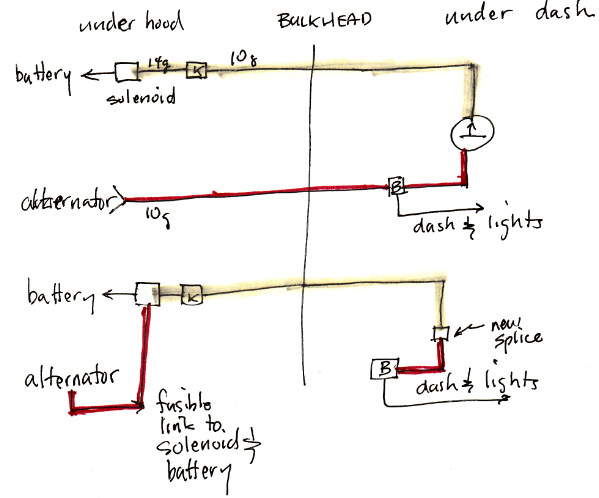
    Ok, so I just found a number of wiring hacks from PO that almost burned my Jeep up. As such, I have decided to re-do much of the wiring on my wagoneer in an attempt to improve safety. Part of my mods will include ammeter delete. I will replace it with a voltmeter due to the improved fire resistance. I also plan on running a 4 ga (or bigger depending on what I have available already) wire from the alternator ?bat? post directly to the constant side of the starter solenoid.

    That brings me to my question.

    When doing this, should I keep the yellow 10 ga wire with the fusible link that would now supply my voltmeter and then link the old ammeter red wire to the same post on the voltmeter in order to feed the factory splice that was downstream of the ammeter and the delete the red 10 ga wire that used to run from the splice to the ?bat? post on the alternator?

    Or

    Delete that entire yellow wire w/ fusible link and run directly a wire from the constant post on the starter solenoid to the splices and then tap a wire from the splice to the voltmeter?

    Lastly, should any of this be run thru a circuit breaker or fuse? I have a spare marine 100A and 150A breaker I could add to this system somewhere, but where to put it.

    I know this mod has been done (as I?ve read a number of posts) but I don?t see anything specific about which wires to keep/delete. I also am planning on keeping the stock alternator for now, but will likely upgrade to a bigger one in the future, so whatever I do now I would like to have it future proof (as much as possible).

    Thanks for any help.
    -Andy Stutz-
    '79 Wag

    Specs:
    360 w/ alum intake & 4bbl Carter, TFI conversion, TH400, Cable Shifted Part Time QT w/ 16%OD, 6" BJs all spring, 35" Goodyear MTs, Custom Front Pre-runner style winch bumper w/ M8000, Ford Taurus electric fan, Rear Mini-spool.

    Coming Soon: New floors, FITech EFI with G surge tank, MSD box
  • PlasticBoob
    All Makes Combined
    • Jun 30, 2003
    • 4007

    #2
    I'm going off of memory here, but I believe you keep the main red wire that goes through the bulkhead to the "Big Splice" under the dash. This is a welded junction that was wrapped in duct tape from the factory, IIRC, and feeds everything else. Keeping the yellow wire instead is backwards and inelegant.

    At the end of the red wire, solder on a fusible link. You DO NOT want a fuse in there, because the vehicle will be instantly disabled by small surges or very brief large loads that are pulled by turning on a bunch of power-hungry devices all at once.

    So yes, delete the yellow wire completely, and move the red wire from the alternator BAT terminal over to the "always hot" solenoid post with a fusible link as close to it as practical.

    One more tip - a resettable heavy duty circuit breaker between the alternator BAT terminal and the battery or solenoid is recommended.
    Rob
    1974 Cherokee S, fuel injected 401, Trans-am Red, Aussie locker 'out back'
    Click for video

    Comment

    • flatlander58
      232 I6
      • Jul 11, 2006
      • 88

      #3
      Thank you for the response. I am just wondering why I get rid of the yellow that already has a fusible link only to put one into the red wire? Is it inelegant to just keep the yellow wire because the voltmeter would essentially tap into in the line feeding the splice? Also, the duct tape over all the splices under the dash is factory!?!

      I get the slow vs quick part of a fusible link vs a fuse, but where does a resettable breaker fall (fast or slow)? I’m thinking I could install a 150A breaker between alternator bat post and starter hot post like you recommend, and then install the 100A breaker in the red power feed to the splice under dash and delete the yellow wire, unless anyone sees any issue with that plan. I just like the idea of a resettable breaker instead of a fusible link because if something shorts, I could fix the issue and just reset the breaker and I’m back on the road/trail, but still protected. If a breaker pops too fast though, will go with the link because I don’t want to be resetting it all the time (and thinking I have a short when I don’t).

      Thank you again for the help guys/gals.
      Last edited by flatlander58; 03-21-2018, 05:52 AM.
      -Andy Stutz-
      '79 Wag

      Specs:
      360 w/ alum intake & 4bbl Carter, TFI conversion, TH400, Cable Shifted Part Time QT w/ 16%OD, 6" BJs all spring, 35" Goodyear MTs, Custom Front Pre-runner style winch bumper w/ M8000, Ford Taurus electric fan, Rear Mini-spool.

      Coming Soon: New floors, FITech EFI with G surge tank, MSD box

      Comment

      • flatlander58
        232 I6
        • Jul 11, 2006
        • 88

        #4
        Additionally, if I delete the yellow wire with the fusible link, should I tap the red (sensing?) wire from the alternator 2-wire connector into the 10 ga red wire (previously attached to the alternator bat post) that would be feeding the splice (currently the small red wire from the alternator splices into the yellow wire) or should that alternator sensing wire tap in elsewhere?
        -Andy Stutz-
        '79 Wag

        Specs:
        360 w/ alum intake & 4bbl Carter, TFI conversion, TH400, Cable Shifted Part Time QT w/ 16%OD, 6" BJs all spring, 35" Goodyear MTs, Custom Front Pre-runner style winch bumper w/ M8000, Ford Taurus electric fan, Rear Mini-spool.

        Coming Soon: New floors, FITech EFI with G surge tank, MSD box

        Comment

        • tgreese
          • May 29, 2003
          • 11682

          #5
          I think you're on the wrong track if you delete the yellow wire. I made a drawing showing before and after -

          I did this from memory and the wiring diagram, but I have bypassed my '82 in this manner. Is this clear? Splices B and K are shown in the wiring diagram. I left the original fusible link and re-purposed the red 10 ga wire by unplugging it from the bulkhead connector, inserting a second fusible link, and connecting to the battery terminal of the solenoid. I think I abandoned-in-place the red wire from splice B to the bulkhead connector, and only removed the wire from the bulkhead connector under the hood. The 14 ga wire in the "before" drawing is the original fusible link, and it's not changed. The sense and excite wires to the alternator are not changed.


          Last edited by tgreese; 03-21-2018, 08:11 AM.
          Tim Reese
          Maine beekeeper's truck: '77 J10 LWB, 258/T15/D20/3.54 bone stock, low options (delete radio), PS, hubcaps.
          Browless and proud: '82 J20 360/T18/NP208/3.73, Destination ATs, 7600 GVWR
          Copper Polly: '75 CJ-6, 304/T15, PS, BFG KM2s, soft top
          GTI without the badges: '95 VW Golf Sport 2000cc 2D
          ECO Green: '15 FCA Jeep Cherokee KL Trailhawk

          Comment

          • tgreese
            • May 29, 2003
            • 11682

            #6
            IMO the fusible link is perfectly appropriate here - no need for a fuse. It's not supposed to be readily replaceable. Instead it's meant to protect the car from burning up in case of a catastrophe like a wreck.

            I doubt that you need as heavy a wire as a #4. Most generic battery cables are #4 wire. I would burn that bridge when I came to it by using the existing 10 ga wire until I was ready to upgrade the alternator. That's fine for any 10SI you might have, especially considering the short length and exposed routing of the wire.
            Last edited by tgreese; 03-21-2018, 09:02 AM.
            Tim Reese
            Maine beekeeper's truck: '77 J10 LWB, 258/T15/D20/3.54 bone stock, low options (delete radio), PS, hubcaps.
            Browless and proud: '82 J20 360/T18/NP208/3.73, Destination ATs, 7600 GVWR
            Copper Polly: '75 CJ-6, 304/T15, PS, BFG KM2s, soft top
            GTI without the badges: '95 VW Golf Sport 2000cc 2D
            ECO Green: '15 FCA Jeep Cherokee KL Trailhawk

            Comment

            • flatlander58
              232 I6
              • Jul 11, 2006
              • 88

              #7
              Thanks for the diagram tgreese. I think that what you did was what I originally was thinking (except your ?new splice? between red and yellow under the dash would be the + post of my voltmeter, with the other voltmeter post going to ground). I think I may still do the 150A resettable breaker between the alternator and battery (where you say to add the fusible link). I may reconsider the 4 ga. I may do 8 ga instead. I would like that to be a bit bigger than 10 ga since it will be carrying full alternator charging load to the battery (true only 63 Amps now, but in the future may be over 100A with a new alternator). I guess I will leave the original fusible link in the yellow wire instead or a breaker though, at least for now. If the link didn?t blow when carrying the alternator load, I suppose it isn?t likely to blow under the new configuration unless a significant short were to occur. Thanks again for all the help guys.
              -Andy Stutz-
              '79 Wag

              Specs:
              360 w/ alum intake & 4bbl Carter, TFI conversion, TH400, Cable Shifted Part Time QT w/ 16%OD, 6" BJs all spring, 35" Goodyear MTs, Custom Front Pre-runner style winch bumper w/ M8000, Ford Taurus electric fan, Rear Mini-spool.

              Coming Soon: New floors, FITech EFI with G surge tank, MSD box

              Comment

              • PlasticBoob
                All Makes Combined
                • Jun 30, 2003
                • 4007

                #8
                Thank you for the response. I am just wondering why I get rid of the yellow that already has a fusible link only to put one into the red wire?
                My TSM lists the red wire as the "battery feed - unfused alternator output" whereas the yellow wire is only listed as the "bulkhead to ammeter negative." In the stock configuration, if the ammeter breaks in a certain way, no battery power is able to make it to the Big Splice from the yellow wire at all, and the Jeep completely dies. I've experienced this in a friend's truck. Keeping the yellow wire (#55 on my wiring diagram) and using it to feed the entire cab is inelegant because the "flow" of electricity should be first to the Big Splice (#12, unfused alternator output), which is red. When charging, the Big Splice feeds EVERYTHING inside the truck; when charging, power was meant to flow from the alternator to the Big Splice, and then trickle out through the yellow wire to charge the battery. The yellow wire, at least on my '74, carries the charge delivered from the Big Splice from the ammeter to the battery, and supplies the Big Splice "backwards" during periods of no charge or discharge. If you think about it, it makes no sense that the yellow wire is protected, but the red one is not. This is why we have the meltdown/fire in the first place. Maybe there is no size fusible link that can protect the red wire during large charges?

                So in order to keep the yellow wire, you need to either leave the cab-end connected to the same post as the red wire on the ammeter, or solder them together, and now you're still running an old (and potentially corroded/beat up) fusible link, and you also now have a mustard-and-ketchup frankenstein main feed wire. That's less than acceptable to me, but it will work. I just think it's better to have a brand new fusible link soldered onto a feed wire that is the same color as the wires supplying the rest of the truck from the Big Splice.

                I was advised by Joe Guilbeau, the resident electrical genius here back in the day, to do it this way. It's been working great for over 15 years with no issues.

                Here's a diagram of the flow of charge. When you use the yellow wire as a feed, during charging you reverse all of this. That doesn't make any sense to me, especially having to have a main feed wire that now has two different colors. It's not wrong, and it will work, but just doesn't seem very clean or logical.


                Is it inelegant to just keep the yellow wire because the voltmeter would essentially tap into in the line feeding the splice?
                See above. You can plug the voltmeter in wherever you want, but I would put it as far "down the line" as possible - the closer the voltmeter feed is to the cab input wire (yellow or red), the higher it will read. I prefer tapping it into circuits far removed from the feed, so it reads a little low (theoretically). In practice, it doesn't really matter that much.

                Also, the duct tape over all the splices under the dash is factory!?!
                What do you think this is, a Toyota? lol

                I get the slow vs quick part of a fusible link vs a fuse, but where does a resettable breaker fall (fast or slow)?
                The breaker is fast, just like a fuse, except that you can reset it quickly and reuse it.

                then install the 100A breaker in the red power feed to the splice under dash and delete the yellow wire, unless anyone sees any issue with that plan. I just like the idea of a resettable breaker instead of a fusible link because if something shorts, I could fix the issue and just reset the breaker and I’m back on the road/trail, but still protected. If a breaker pops too fast though, will go with the link because I don’t want to be resetting it all the time (and thinking I have a short when I don’t).
                This would work, but I don't like it because every time it pops, the car will INSTANTLY die and leave you wherever you are. A fusible link will allow you to potentially notice that something is wrong and get off the road before it blows. Also, if you are having issues large enough to pop the breaker, simply resetting it won't stop it from instantly tripping again. As TGreese said, definitely stick with a fusible link.
                Last edited by PlasticBoob; 03-21-2018, 11:05 AM.
                Rob
                1974 Cherokee S, fuel injected 401, Trans-am Red, Aussie locker 'out back'
                Click for video

                Comment

                • nograin
                  304 AMC
                  • Dec 19, 2000
                  • 2286

                  #9
                  You guys have it basically right. I think those are good explanations.

                  The charge circuit (yellow wire with ammeter) was not supposed to be subjected to large charge loads for any length of time. But its large enough to handle them for brief periods, as well as emergency driving with the alternator dead or weak.

                  The fusible link should be sized to protect the smallest wire between the battery and fusebox or ground, whichever comes first. They protect against a battery short to ground. Lets say its a fully charged battery rated at 550 cca. Think what that means if there's a short downstream. Yup. that's a lot of power thats going to seek ground given a chance.

                  If you look at the late model SJs ('86 - '91) with much of the main junction moved to the engine compartment, there's a bunch of fusible links. You can get some idea of wire sizing from those as well. The earlier design is simpler, but it has its limitations.
                  '85 Grand Wagoneer
                  360 727auto, NP229
                  body by beer (PO)
                  carries wood inside
                  no "wood" outside
                  My other car is a fish

                  Comment

                  • PlasticBoob
                    All Makes Combined
                    • Jun 30, 2003
                    • 4007

                    #10
                    Originally posted by flatlander58
                    I’m thinking I could install a 150A breaker between alternator bat post and starter hot post like you recommend
                    I think an alternator's rating is for the absolute maximum output possible, so it would probably be a better bet to install a circuit breaker that is in the same ballpark. For example, my CS130 alternator is (I believe) rated at 105 amps, and my circuit breaker is rated at 100 amps. Not a perfect match, but I haven't had it trip a single time in over 10 years.

                    Something like this: https://www.amazon.com/Bussmann-CB18.../dp/B00139FQSS
                    Rob
                    1974 Cherokee S, fuel injected 401, Trans-am Red, Aussie locker 'out back'
                    Click for video

                    Comment

                    • tgreese
                      • May 29, 2003
                      • 11682

                      #11
                      This is a scrap from the 1976 CJ wiring diagram. A '75-up CJ with a 232 or 258 has the same equipment as we are trying to wire up for the Wagoneer: voltmeter and 10SI alternator. This diagram is how Jeep would wire up the Wagoneer in question.


                      Notice that this diagram has two fusible links, just like the diagram I posted above. The 10 ga wire 12C goes through the bulkhead connector and to a splice under the dash (splice "P"). You can look at the complete diagram here - http://oljeep.com/gw/76_tsm/Section22.pdf

                      I can't argue with Rob's wanting to have all the wiring the same color - it's all red here - but it seems a lot of effort for something that's never going to be seen. Plus, I think there's some value in keeping the wire color that's already present in the car. Make a good crimp, solder and use adhesive heat shrink for an excellent splice.

                      I also think nograin has a good point, that the fusible link is meant to prevent a catastrophe when the battery shorts to ground. The ammeter fire comes from high resistance in the ammeter and is driven by the alternator output.

                      I know you can get at least a 12 ga fusible link that will protect 8 ga wire. Larger sizes may be available.
                      Last edited by tgreese; 03-22-2018, 11:56 AM.
                      Tim Reese
                      Maine beekeeper's truck: '77 J10 LWB, 258/T15/D20/3.54 bone stock, low options (delete radio), PS, hubcaps.
                      Browless and proud: '82 J20 360/T18/NP208/3.73, Destination ATs, 7600 GVWR
                      Copper Polly: '75 CJ-6, 304/T15, PS, BFG KM2s, soft top
                      GTI without the badges: '95 VW Golf Sport 2000cc 2D
                      ECO Green: '15 FCA Jeep Cherokee KL Trailhawk

                      Comment

                      • nograin
                        304 AMC
                        • Dec 19, 2000
                        • 2286

                        #12
                        Originally posted by PlasticBoob
                        I think an alternator's rating is for the absolute maximum output possible, so it would probably be a better bet to install a circuit breaker that is in the same ballpark. For example, my CS130 alternator is (I believe) rated at 105 amps, and my circuit breaker is rated at 100 amps. Not a perfect match, but I haven't had it trip a single time in over 10 years.

                        Something like this: https://www.amazon.com/Bussmann-CB18.../dp/B00139FQSS
                        No!
                        The purpose of a fuse or breaker is to protect the weakest links in the circuit. They are sized based on the wiring or device drawing load.
                        '85 Grand Wagoneer
                        360 727auto, NP229
                        body by beer (PO)
                        carries wood inside
                        no "wood" outside
                        My other car is a fish

                        Comment

                        • nograin
                          304 AMC
                          • Dec 19, 2000
                          • 2286

                          #13
                          The ammeter fire comes from high resistance in the ammeter and is driven by the alternator output.

                          I know you can get at least a 12 ga fusible link that will protect 8 ga wire. Larger sizes may be available.
                          Yes. and yes and I agree with the rest of your post as well.

                          I drew up some diagrams to illustate how a fusible link works in an ammeter type system. Concept isn't really that different when the charging circuit is moved. So maybe that page will be helpful to all.

                          Also, for those with an ammeter, I put together a page about how the circuit works and what to do to avoid problems. Too many times here I've read about the fusible link being bypassed, trying to drive with the ammeter needle pegged, or 'just' adding a few electric accessories to the battery.
                          Last edited by PlasticBoob; 03-22-2018, 10:34 PM. Reason: Edited for visibility
                          '85 Grand Wagoneer
                          360 727auto, NP229
                          body by beer (PO)
                          carries wood inside
                          no "wood" outside
                          My other car is a fish

                          Comment

                          • PlasticBoob
                            All Makes Combined
                            • Jun 30, 2003
                            • 4007

                            #14
                            Originally posted by nograin
                            No!
                            The purpose of a fuse or breaker is to protect the weakest links in the circuit. They are sized based on the wiring or device drawing load.
                            Gotcha, with some questions! Wouldn't you also take into account the maximum output of the alternator? Say you have a CS144 that puts out 140 amps max and all your wiring is spec'd properly. Then you pull a 110 amp load - a 100 amp BAT breaker would blow every time you pull that load, wouldn't it? Or does the battery help reduce it by discharging? So then you'd need a 140 amp breaker? I guess I am coming at it from a different angle?

                            Also, doesn't a breaker on the alternator BAT output prevent damage from an alternator that goes crazy and starts putting out huge amounts of amperage? Or is it there to prevent the alternator from being damaged by the rest of the system pulling a load from it that is beyond its rated output? Or both?
                            Rob
                            1974 Cherokee S, fuel injected 401, Trans-am Red, Aussie locker 'out back'
                            Click for video

                            Comment

                            • nograin
                              304 AMC
                              • Dec 19, 2000
                              • 2286

                              #15
                              Originally posted by PlasticBoob
                              Gotcha, with some questions! Wouldn't you also take into account the maximum output of the alternator?
                              No. We don't care how big the source is. We can have a 700 CCA battery and we don't change our wiring.
                              Say you have a CS144 that puts out 140 amps max and all your wiring is spec'd properly. Then you pull a 110 amp load - a 100 amp BAT breaker would blow every time you pull that load, wouldn't it?
                              yes.
                              Or does the battery help reduce it by discharging? So then you'd need a 140 amp breaker? I guess I am coming at it from a different angle?
                              You're asking the right questions because many of us have been misled here. See if this makes sense.
                              The current flows from the highest potential. When the engine is running, this is the alternator. Only time the battery will help is when the alternator's output is exceeded. This happens with accesories like a winch which have huge power demands, and the voltage gets pulled down when this the winch is running. Lets leave the winch and plow situations aside and go to how the potential works.

                              Batteries have between 11 Volt when low and 13+ Volts when fully charged.
                              Alternators should be running around 14 Volts, sometimes a little less, usually 14.2 to 14.8 V depending on temperature, rpm and the type of regulator.
                              When we measure 14.2 volts at the battery positive, that's system voltage. It's coming from the alternator. As soon as the engine is shut off, it drops to the high 13s, until the surface charge disapates and we see its fully charged voltage, say 12.8 Volts.

                              The only way to know if the battery is being charged while the alternator is running is with an ammeter. The voltage just tells us that the potential is there to do the job. Once the battery is recharged, no current flow to it. Internally it will never reach 14, but it will develop a surface charge that floats closer to 14+ Volts in the system when the alternator is running).

                              Alternator Output
                              Related to what you are trying to get at, the alternator's max output will be available at high rpm. The power output of interest to us (and most older automobiles) is from idle and just off idle. For us, electrical demands at idle are about the same as when at high rpm. Only the ingition system may have a little more power demand at higher rpm and load, and thats 2 to 4 amps more at most.

                              Also, doesn't a breaker on the alternator BAT output prevent damage from an alternator that goes crazy and starts putting out huge amounts of amperage? Or is it there to prevent the alternator from being damaged by the rest of the system pulling a load from it that is beyond its rated output? Or both?
                              Alternator output will only be what is asked of it. It never exceeds the demand. If its 14.5 volts and a 5 watt light bulb is attached, it will provide 5 watts at 14.5 volts. If there is a short to ground, both the battery and the alternator will discharge as much as the connections and wiring will allow. [That's close to what I illustrated on this page. Because the SI alternators are self feeding, we probably should make another diagram showing that situation.]

                              Alternators current output is limited by rpm and the current flowing through the primary windings. Remember, its basically just an electromagnet. The rotor winding is a spinning electromagnet. The current flowing through the rotor's windings is controlled by the voltage regulator. The output is the current induced in the non-moving windings. But if there is no demand, there is no current out. It has potential - 14.5 volts, but there is no flow.
                              Last edited by nograin; 03-23-2018, 07:06 AM.
                              '85 Grand Wagoneer
                              360 727auto, NP229
                              body by beer (PO)
                              carries wood inside
                              no "wood" outside
                              My other car is a fish

                              Comment

                              Working...
                              X