Megasquirt2 Install AMC360 TBI 83' Cherokee

Collapse
This is a sticky topic.
X
X
 
  • Filter
  • Time
  • Show
Clear All
new posts
  • myk
    232 I6
    • Jan 30, 2011
    • 82

    Megasquirt2 Install AMC360 TBI 83' Cherokee

    Hello,

    Thought I'd start this thread up to document my installation of a Megasquirt 2 system on my 83' laredo with the 360 engine, engine is .030 over 9.5cr, heads cleaned up a bit, mild cam, headers, performer AMC intake and a bit of a stall converter in the 727 trans:

    Hello, first post here, thought I'd post some pictures of my project. It's an 83' cherokee laredo that we've had in the family since new, I beat the hell of of this thing way back in highschool, one tough rig. About 12 years ago I ended up rebuilding the 360 and all the drivetrain, putting the 6" lift springs and 35 tires


    So far I have most everything needed:

    MS2
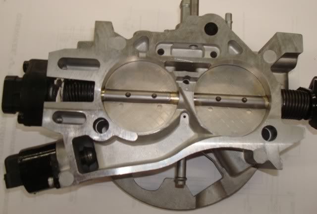
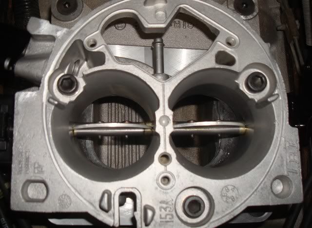
    GM 454TBI 2" bores w/ stepper IAC
    Walbro 255lph pump
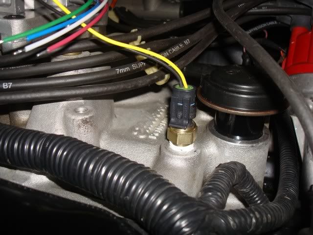
    Various Sensors (IAT, CLT, TPS, Fuel Pressure)

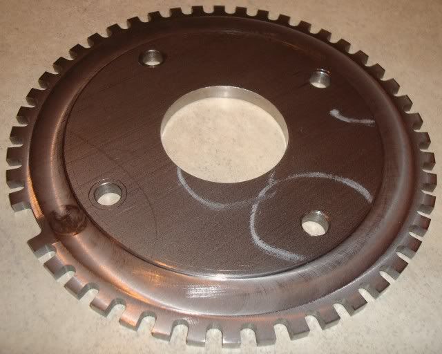
    I'm planning on using a 36-1 toothed wheel on the crank pulley for the tach signal plus a one tooth sensor in the distributor both using Allegro gear tooth sensors (had great experience with this setup on past installs)

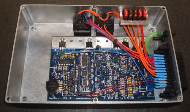
    Right now I am just finishing up the ECU, I wanted to put it in the engine compartment mounted on top of the driverside inner fender well. This facilitated the need to make it watertight which I accomplished with a hammond enclosure and the ampseal 35 pin plug, check out the details below:


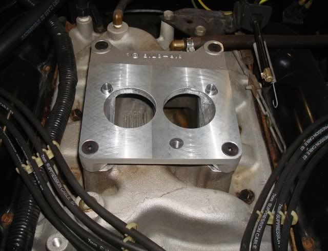
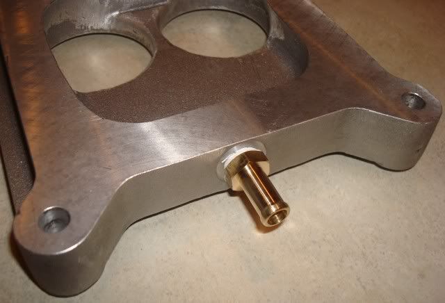
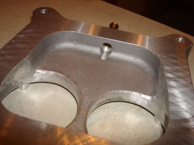
    Next up will be fitting the TBI to my edelbrock performer AMC intake, not sure if the sides will need to be clearanced for the 2" throttle bores or not, I've read conflicting reports here. Then the gas tank mods and fitting the pump and filters and finishing up the wiring. This will have ignition control as well, but I will get it running first on fuel only then tackle the ingnition after that.....more to come

    Mike
    Last edited by myk; 11-03-2011, 12:43 PM.
  • Greeeeenberg
    232 I6
    • Sep 13, 2010
    • 32

    #2
    Awesome. Subscribed. I want to do this to my GW. You gonna hook it up before you convert over to do some data-logging with your current setup?
    '87 Grand Wagoneer - 360
    '97 ZJ Orvis Edition - 318

    Comment

    • myk
      232 I6
      • Jan 30, 2011
      • 82

      #3
      Originally posted by Greeeeenberg
      Awesome. Subscribed. I want to do this to my GW. You gonna hook it up before you convert over to do some data-logging with your current setup?
      I'll just go straight to the fuel setup, this will be the fourth one I've done in the last 4 years using MS2 so I'm pretty comfortable with it.

      I was looking around for a base ignition map for the 360 if anone has anything out there already setup? otherwise I'll just have to start with the sbc map and tweak it.

      Thanks for the compliments, appreciate it.

      Mike

      Comment

      • chrism
        327 Rambler
        • Apr 07, 2002
        • 634

        #4
        If I can find the bin from my last 360 tbi install I will try to extract the spark table from it. It worked pretty well on a stock 360. Its been a while but I think its on my tuning laptop.
        1979 Cherokee
        1979 CJ-7

        Comment

        • myk
          232 I6
          • Jan 30, 2011
          • 82

          #5
          Originally posted by chrism
          If I can find the bin from my last 360 tbi install I will try to extract the spark table from it. It worked pretty well on a stock 360. Its been a while but I think its on my tuning laptop.
          That would be great, anything from the 360 would be a better starting point, thanks.

          Mike

          Comment

          • myk
            232 I6
            • Jan 30, 2011
            • 82

            #6
            Finally making some progress.

            The throttle body and adapter plate was a ton of work to get right. The 454 tbi unit I got off ebay needed the throttle shaft fixed, ended up being a bigger job than I anticipated, but turned out great, actually ended up silver soldering material onto the shaft and turning it back to size to match the housing. I did this because the bores in the housing were nice and round, the shaft on the other hand was all worn out and needed to be replaced or fixed so I just did all the repair on the shaft and left the housing alone.

            Then the holley 17-45 adapter plate I got from Summit came and when I bolted the tbi unit to it the throttle bores were off from the holes in the adapter plate by .10". Not sure what the deal was on this?? so I ended up plugging the existing holes with 1/4" pipe plugs and refacing the plate and putting the new holes in the proper spot. Lines up perfect now and I also put some alignment bushings in the aft two holes. The tbi was already counterbored for these from the factory, this makes it nice to line things up, gaskets, etc.

            Also did a bunch of blending work on the adapter and performer manifold to get them all to flow nice together. Lots of work but it turned out the way I wanted it.

            Also finished up the Megasquirt water tight case and tested it out on the bench, all circuits performed as expected. Going to mount the ECU on top of the driver side inner fender well in the engine bay.

            Next step will be installing the ECU and working out the crank trigger, fuel supply, throttle/kickdown linkage and the wiring harness. Fun stuff

            P.S. Still looking for an ignition timing map if anyone has anything to start with? thx

            Mike


            Last edited by myk; 03-13-2011, 10:40 PM.

            Comment

            • myk
              232 I6
              • Jan 30, 2011
              • 82

              #7
              Finished up the throttle linkage and the tranny linkage tonight, glad that's over.

              I cut the stock throttle bracket up quite a bit and welded it back together to get it in the correct spot, also added a gusset to it to stiffen things up. The gm tbi has a small pin sticking out of it where the throttle would attach, I ground this off flush where it meets the larger diameter then drilled an tapped it for a 10-32 thread, then threaded the ball stud from my holley carb setup into there with some loctite.

              The tranny linkage was pretty straightforward, I fabbed up a small bracket to attach to the lower part of the tbi throttle shaft, attached it with two small bolts and nuts, then added the stud at the bottom again from my carb that picks up the stock tranny kickdown/throttle valve linkage, worked out perfect. The distance from the center of the throttle shaft to the pivot is 1.2" which I copied from my holley carb. The linkage is maxed out at full throttle and has ~3/8" slack when the throttle is closed, seems about right.

              I had that return spring on my holley carb as well and added it to the tbi but I'm not sure it's needed, the tbi itself has some pretty mean springs on it, that together with the tranny linkage makes it feel about right, with the additional spring on there it seems too stiff to me. What have some of you guys done for return springs with the tbi? wonder if GM used a return spring in addition to the tbi springs?

              Mike


              Comment

              • tgreese
                • May 29, 2003
                • 11682

                #8
                That case looks like a standard cast aluminum project box. Those are great for this purpose; much better than the case supplied with the MS kit, I'd think. There is a line of these boxes that has a silicone gasket in the lid - is that what you used? How did you seal the penetrations?

                Looks like the PCV port comes out of the front of the TB - darned inconvenient for the AMC app.
                Last edited by tgreese; 03-16-2011, 09:34 AM.
                Tim Reese
                Maine beekeeper's truck: '77 J10 LWB, 258/T15/D20/3.54 bone stock, low options (delete radio), PS, hubcaps.
                Browless and proud: '82 J20 360/T18/NP208/3.73, Destination ATs, 7600 GVWR
                Copper Polly: '75 CJ-6, 304/T15, PS, BFG KM2s, soft top
                GTI without the badges: '95 VW Golf Sport 2000cc 2D
                ECO Green: '15 FCA Jeep Cherokee KL Trailhawk

                Comment

                • tgreese
                  • May 29, 2003
                  • 11682

                  #9
                  Read your link - good work! Thanks for posting the PNs for the connector.

                  I used one of these cases for my Duraspark/HEI installation. Good stuff.
                  Tim Reese
                  Maine beekeeper's truck: '77 J10 LWB, 258/T15/D20/3.54 bone stock, low options (delete radio), PS, hubcaps.
                  Browless and proud: '82 J20 360/T18/NP208/3.73, Destination ATs, 7600 GVWR
                  Copper Polly: '75 CJ-6, 304/T15, PS, BFG KM2s, soft top
                  GTI without the badges: '95 VW Golf Sport 2000cc 2D
                  ECO Green: '15 FCA Jeep Cherokee KL Trailhawk

                  Comment

                  • myk
                    232 I6
                    • Jan 30, 2011
                    • 82

                    #10
                    Originally posted by tgreese
                    That case looks like a standard cast aluminum project box. Those are great for this purpose; much better than the case supplied with the MS kit, I'd think. There is a line of these boxes that has a silicone gasket in the lid - is that what you used? How did you seal the penetrations?

                    Looks like the PCV port comes out of the front of the TB - darned inconvenient for the AMC app.
                    The case is a Hammond 1550WGBK it's a little bigger than needed but there's lots of room on the fender well so it's not an issue. It comes with a nice watertight seal on the lid. I've used a similar one on my yamaha quad efi conversion. The newer boxes actually have a replaceable seal on the lid which I like better, the molded silicone seals tends to wear out over time, the one on my quad has seen better days.

                    The main connector is an ampseal 35 pin connector which is waterproof, these are great automotive grade connectors, I wish the megasquirt had provisions for these right from the get go. The rest of the penetrations are just some small screws that are silicone sealed and two bulkhead connectors. In the link above you can see where I submerged the thing for 15min underwater and it was dry as a bone when I took it out.

                    And yeah, why didn't GM put that PCV port in the back for me 
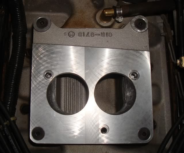
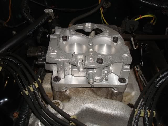
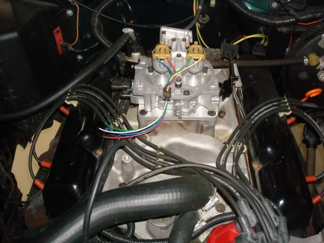
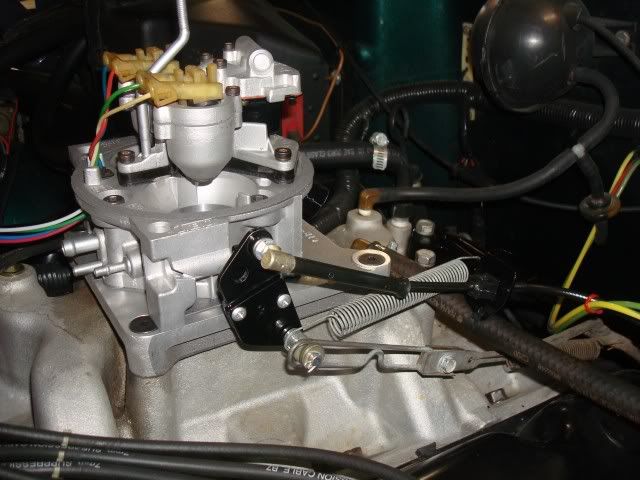
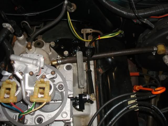
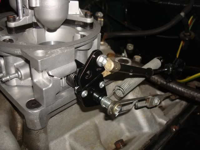
I'm going to take the adapter plate back off and put a fitting in the back of it for the PCV and just block off all the tbi ports in the front. There is one port in the back of the tbi that I will use for the MAP sensor.
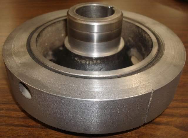
                    Also did some searching and found that GM did not use a throttle return spring on the TBI units, so I took that spring off and am just going to use the two built in torsion springs on the TBI itself, they seem more than enough.

                    Mike

                    Comment

                    • tgreese
                      • May 29, 2003
                      • 11682

                      #11
                      Originally posted by myk
                      ...
                      Also did some searching and found that GM did not use a throttle return spring on the TBI units, so I took that spring off and am just going to use the two built in torsion springs on the TBI itself, they seem more than enough.
                      The concentric return springs should put less lateral force on the throttle shaft and it will wear less. A good thing ...
                      Tim Reese
                      Maine beekeeper's truck: '77 J10 LWB, 258/T15/D20/3.54 bone stock, low options (delete radio), PS, hubcaps.
                      Browless and proud: '82 J20 360/T18/NP208/3.73, Destination ATs, 7600 GVWR
                      Copper Polly: '75 CJ-6, 304/T15, PS, BFG KM2s, soft top
                      GTI without the badges: '95 VW Golf Sport 2000cc 2D
                      ECO Green: '15 FCA Jeep Cherokee KL Trailhawk

                      Comment

                      • myk
                        232 I6
                        • Jan 30, 2011
                        • 82

                        #12
                        A bit more progress this weekend:

                        I got the balancer removed from the engine and machined the back of it to accept the crank trigger wheel, I'll machine up the trigger wheel this week, it will press on the back of the balancer hub, probably going to make a 36-1 or 48-1 wheel, I'll see how much room I have when I get it drawn up.

                        Also got the temp sensor installed in the manifold, there was a perfect unused spot for it in the edelbrock intake. Ended up draining the radiator and removing it from the jeep since the side brackets were broke off where they get soldered to the radiator up top, going to take that into a radiator shop tomorrow to get that fixed up while I'm at it.

                        Started in on the gas tank removal but didn't get too far on that yet.

                        Here's some pics of the balancer and temp sensor.


                        Comment

                        • myk
                          232 I6
                          • Jan 30, 2011
                          • 82

                          #13
                          Finished up the trigger wheel tonight, ended up going with a 48-1 wheel since I had the room for it. Machined a step in the fwd face to keep the teeth away from the portion of the balancer that is ouside the rubber ring since it probably moves a bit when the engine is running.

                          Also added a PCV port to the back of the holley TBI adapter so I didn't have to run a hose from the front of the TBI all the way to the back of the manifold, now it can run right from the back. Also picked up a pack of rubber caps to block off the unused ports in the front of the TBI.

                          Next up I'll fab up a bracket for the hall sensor, planning on making it a combo bracket with the fuel pump block off plate. Then I can press the trigger wheel on the balancer hub and re-install everything. Got my radiator back from the shop today too.

                          Mike


                          Comment

                          • PlasticBoob
                            All Makes Combined
                            • Jun 30, 2003
                            • 4007

                            #14
                            That's amazing work! Any word on whether or not you can make me a wheel and bracket, and if so, how much they would run?

                            I know nothing about machining, what specifically did you have to do to the balancer (so I can tell the machine shop what to do)?
                            Rob
                            1974 Cherokee S, fuel injected 401, Trans-am Red, Aussie locker 'out back'
                            Click for video

                            Comment

                            • myk
                              232 I6
                              • Jan 30, 2011
                              • 82

                              #15
                              Originally posted by PlasticBoob
                              That's amazing work! Any word on whether or not you can make me a wheel and bracket, and if so, how much they would run?

                              I know nothing about machining, what specifically did you have to do to the balancer (so I can tell the machine shop what to do)?
                              Thanks Rob,

                              I hind site I don't think I would do it this way again, it was a major pain. What I didn't realize is that the front cover of the engine slopes forward in the area right above and behind the balancer, I ended up having an interference with the cover and the trigger wheel of ~.10". I couldn't see this when I was planning it out originally. I had to pull the balancer back off and make a .10" thick spacer between the crank and the balancer and then machine off .10" from the front of the balancer where the pully attaches so that it would be in the same place and have the belts align properly. I also clearanced the front cover a bit in the area of the interference just to be on the safe side. It turned out good but was a lot of work.

                              If I were you I would just order the 6 3/4" wheel that diyautotune sells for $29 and sandwich it between the balancer and the pulley. Take it to a machine shop and have them take an 1/8" off the front of the balancer to make up for the thickness of the trigger wheel. There's lots of thread depth in the balancer hub so don't worry about removing some material there.

                              The bracket is just one of those deals your going to have to fab up with some plate and a welder. I was laying that all out tonight and it's fairly straighforward but it needs to be custom fit on the jeep. I'll post up some pics of mine installed tomorrow.

                              Mike
                              Last edited by myk; 03-24-2011, 11:36 PM.

                              Comment

                              Working...
                              X