Ammeter to Voltmeter Questions

Collapse
X
 
  • Filter
  • Time
  • Show
Clear All
new posts
  • NBD925
    232 I6
    • Oct 16, 2014
    • 124

    Ammeter to Voltmeter Questions

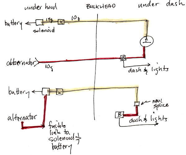
    I have redone my instrument cluster and installed a new Voltmeter where the Ammeter was. Trying to prevent a possible fire! I am trying to work out the correct wiring under the dash and at the Alternator. I hooked both the old wires (Yellow and Red) under the dash, to the positive post of the New Voltmeter and Installed a new Ground Wire from the negative post to a good ground under the dash. Now I am trying to figure out how to hook up my Alternator.

    Do I leave the old red wire from the alternator connected at the alternator post (making a connection up to the dash Voltmeter) and add a new larger gauge wire to the same alternator post connecting the alternator to the battery? Is that correct?

    Maybe I’m over thinking it but I don’t want to blow anything up.
    Last edited by NBD925; 05-21-2018, 05:20 PM.
    1977 Jeep J10
    258 Engine
    Weber 38 carb
    T15 Trans
    Dana 20 with Tera Low
    Dana 44 Front and Rear axles
    Custom 16 inch rims 235x85 R16 Duratrac tires
  • NBD925
    232 I6
    • Oct 16, 2014
    • 124

    #2
    I think I found the answer. Look at the image in post #52. This shows a good diagram for wiring the Voltmeter correctly. I think, I am going to Remove the yellow wire from the soloniod (cap it) and also disconnect it from the Voltmeter post (combined with the red wire) and cap it there as well.

    Here is a link to the post #52

    Well, I did the Ammeter bypass today...took about 40 minutes...cost about $28 bucks (I went for the Heavy duty 100 amp fuse). I did this with pics just b/c I had a camera available. Items: 100 amp self tripping/reset (like in your house) waterproof fuse-$19-Autozone (use a 100 Amp fuse for a mostly stock electrical system
    1977 Jeep J10
    258 Engine
    Weber 38 carb
    T15 Trans
    Dana 20 with Tera Low
    Dana 44 Front and Rear axles
    Custom 16 inch rims 235x85 R16 Duratrac tires

    Comment

    • tgreese
      • May 29, 2003
      • 11682

      #3
      How I did this - I connected the voltmeter to switched power somewhere on the cluster. This way, the voltmeter will not remain on when you turn the key off. There's no need to have a big wire going to the voltmeter - any source of a positive connection that does not otherwise go to a large load will do. The meter is a very small drain, but it is a drain nonetheless.
      Tim Reese
      Maine beekeeper's truck: '77 J10 LWB, 258/T15/D20/3.54 bone stock, low options (delete radio), PS, hubcaps.
      Browless and proud: '82 J20 360/T18/NP208/3.73, Destination ATs, 7600 GVWR
      Copper Polly: '75 CJ-6, 304/T15, PS, BFG KM2s, soft top
      GTI without the badges: '95 VW Golf Sport 2000cc 2D
      ECO Green: '15 FCA Jeep Cherokee KL Trailhawk

      Comment

      • NBD925
        232 I6
        • Oct 16, 2014
        • 124

        #4
        Interesting, I didn?t think about this small drain. Thanks for the tip. I?ll look into switching that around.
        1977 Jeep J10
        258 Engine
        Weber 38 carb
        T15 Trans
        Dana 20 with Tera Low
        Dana 44 Front and Rear axles
        Custom 16 inch rims 235x85 R16 Duratrac tires

        Comment

        • nograin
          304 AMC
          • Dec 19, 2000
          • 2286

          #5
          Originally posted by NBD925
          I think I found the answer. Look at the image in post #52. This shows a good diagram for wiring the Voltmeter correctly. I think, I am going to Remove the yellow wire from the soloniod (cap it) and also disconnect it from the Voltmeter post (combined with the red wire) and cap it there as well.

          Here is a link to the post #52

          http://www.ifsja.org/forums/vb/showt...hlight=ammeter
          If your objective is to avoid fires then the wires attached to the solenoid need fusible links.


          If the alternator shorts, that 6 gage wire is going to be carrying a bunch of current before it burns through. Its going to be like an arc welder.
          I'm with Tim, no need for 6 gage. If running a winch, plow or other mods, size it for a reasonable maximum charging. Otherwise the factory sizing is about right. Remember charging only takes a few minutes, so its not 100% duty cycle. Winch and plows are little or a lot longer and that's when the original ammeter and charging wires can get overworked.
          '85 Grand Wagoneer
          360 727auto, NP229
          body by beer (PO)
          carries wood inside
          no "wood" outside
          My other car is a fish

          Comment

          • NBD925
            232 I6
            • Oct 16, 2014
            • 124

            #6
            Ok, I have a few more questions. It looks like the alternator field (plug that plugs into the side of the alternator with red and brown wire) gets power to the red wire from a splice in the yellow wire that was connected to the starter solenoid. How are you getting your alternator to work without this power source?

            So If I connect a keyed 12v source to the Voltmeter and a ground the other post. Then cap the old yellow and red wires that used to be connected to the old ammeter posts behind the dash. Next, disconnect the Other ends of those red and yellow wires and cap them. Finally, add a 4 gauge wire connecting the alternator output post to the starter solenoid. Where do I get power for that alternator plug? Would a quick fix be to connect the yellow wire back the the soloniod but keep the dash end capped?
            1977 Jeep J10
            258 Engine
            Weber 38 carb
            T15 Trans
            Dana 20 with Tera Low
            Dana 44 Front and Rear axles
            Custom 16 inch rims 235x85 R16 Duratrac tires

            Comment

            • nograin
              304 AMC
              • Dec 19, 2000
              • 2286

              #7
              You may have noticed his alternator field doesn't get initiated. So you're already ahead

              If all you want to do is have a voltmeter instead of an ammeter, put both hot wires from the ammeter together on the voltmeter's positive stud. Then everything works normal.

              Running a 4 gage wire makes no sense unless, except maybe with a winch and even then it might be trouble. Because with a winch, its still going to be recharging the battery and the battery can onlky take so much current before cooking acid. And if that 4 gage wire grounds for any reason - its arc welding time!

              If you really want to run a direct wire for charging, you could do that in parallel (with a fusible link) to the original; or another way is like Posill88 was describing.

              Fusible links are there to protect against battery grounding. The original pre '86 system only needed one - on the charging wire. The '86 and up designs had to use many - one for each circuit that originates at the solenoid or relay. That's because each one is otherwise unprotected against battery grounding.

              Circuit breakers and fuses are to protect wires and equipment downstream. They are sized base on the smallest wire, connector, or motor in the circuit. How much the alternator can produce is not a factor.

              Fusible Links in Charging Systems
              Last edited by nograin; 05-31-2018, 02:28 PM.
              '85 Grand Wagoneer
              360 727auto, NP229
              body by beer (PO)
              carries wood inside
              no "wood" outside
              My other car is a fish

              Comment

              • NBD925
                232 I6
                • Oct 16, 2014
                • 124

                #8
                I guess I?m confused again.

                I did the Ammeter to Voltmeter gauge swap to prevent fires. My goal is to have a safe working system that is better than original and expandable so adding things like winches and accessories are not an issue. I also wanted to increase the charging system because I was under the impression that the original wires connecting the alternator to the battery for charging were too small of a gauge and to long (gong from the alternator to the dash and then back to the battery)

                I also realized that after connecting the existing wires (red and yellow) that the Voltmeter will be on at all times because it is not connected to keyed power. But if I don?t hook up the yellow wire with the red on the positive Voltmeter post then my alternator will not get power to the field coil.

                I guess more confusion for me is in the Direct charging connection. Running wires in parallel. I guess, I need more information about how that would be done.

                What is wrong with my idea of the 4 gauge wire from the alternator to the starter solonoid post. I guess I could put a fusible link in-line with that connection and be safe right? I though a bigger wire and a shorter connection was better when dealing with an alternator to battery connection.

                If I eventually put a keyed power source to the Voltmeter What is the best way to power the alternator?
                1977 Jeep J10
                258 Engine
                Weber 38 carb
                T15 Trans
                Dana 20 with Tera Low
                Dana 44 Front and Rear axles
                Custom 16 inch rims 235x85 R16 Duratrac tires

                Comment

                • tgreese
                  • May 29, 2003
                  • 11682

                  #9

                  Top is before, below is after.

                  With an ammeter, all the charging current goes from the alternator, to the dash, through the ammeter and back to the through the bulkhead connector to the battery.The only reason for this loop is to show the charging current at the ammeter.

                  Bottom shows the wiring after with the ammeter gone.

                  This drawing shows the ammeter, not the voltmeter. You can connect the voltmeter to any switched connection on the instrument panel, and ground. All the voltmeter does is look at the operating voltage of the car. You can pick that up anywhere convenient, and it does not need to be connected to the charging circuit.

                  Take some time to look at the circuit and understand how it works. Draw it if you need to.

                  Take the big red wire from the alternator and connect it to the battery terminal of the solenoid, adding a fusible link. Under the dash, splice the big red and yellow wires together. Replace or abandon-in-place the ammeter.

                  The alternator field gets power via the resistance wire, which is connected to switched power going to the coil. You do not have to change that. Not sure why you think you have to change that. This is connected to the ignition as part of the "dash & lights" shown above.

                  Re the 4 ga wire, it's just not needed. The existing 10 ga wire is fine, IMO. You need the fusible links to protect the car from a battery short to ground, in case of a catastrophe like a wreck. You need the original fusible link. When you connect the battery to the alternator, you now need a fusible link to protect that connection too.
                  Last edited by tgreese; 06-01-2018, 08:38 AM.
                  Tim Reese
                  Maine beekeeper's truck: '77 J10 LWB, 258/T15/D20/3.54 bone stock, low options (delete radio), PS, hubcaps.
                  Browless and proud: '82 J20 360/T18/NP208/3.73, Destination ATs, 7600 GVWR
                  Copper Polly: '75 CJ-6, 304/T15, PS, BFG KM2s, soft top
                  GTI without the badges: '95 VW Golf Sport 2000cc 2D
                  ECO Green: '15 FCA Jeep Cherokee KL Trailhawk

                  Comment

                  • nograin
                    304 AMC
                    • Dec 19, 2000
                    • 2286

                    #10
                    Exactly what Tim wrote.

                    You're doing good thinking and asking.

                    I also realized that after connecting the existing wires (red and yellow) that the Voltmeter will be on at all times because it is not connected to keyed power.
                    Yes. You are Correct and I was wrong to suggest that because it may be a small drain over time and no one needs that.

                    I did the Ammeter to Voltmeter gauge swap to prevent fires. My goal is to have a safe working system that is better than original and expandable so adding things like winches and accessories are not an issue.
                    The ammeter is a bit of a red herring. The original system was pretty well thought out and has advantages. One is that adding any equipment to the alternator side or fuse panel will not need a fusible link. But this is only an advantage if the alternator can keep up with the demands.

                    I also wanted to increase the charging system because I was under the impression that the original wires connecting the alternator to the battery for charging were too small of a gauge and to long (gong from the alternator to the dash and then back to the battery)
                    This is where the ammeter becomes the red herring. The battery charging normally only takes a few minutes after starting. It may be 20-30 amps for a minute but then drops quickly and should be zero 5 minutes after that. The power for running everything comes from the power source with the highest voltage. The battery is 12.8 to 13.0 when fully charged and under no load. The alternator should be supplying power around 14.2 Volts. Only when it can't supply it at that voltage (too much demand, running too slow, etc) does the battery supply power. That's what the illustrations show here: http://www.heritech.org/cuda/Charge.html

                    But if I don’t hook up the yellow wire with the red on the positive Voltmeter post then my alternator will not get power to the field coil.
                    That's certainly one way to do it. There must be a route for the power from both the battery and the alternator output to get to the voltage regulator and field when the key is on. With a self-exiting 10 or 12SI alternator, there also must be resistance in the field line or it may backfeed and power the ignition when the key is off.

                    I guess more confusion for me is in the Direct charging connection. Running wires in parallel. I guess, I need more information about how that would be done.
                    Off the top of my head, two ways.
                    For what you're doing; If you run a wire from the alternator output stud to the solenoid's battery connection (with fusible link). This would in parallel to the original path. Most of the power to the main junction would still flow direct from alternator to the main junction. This is what Pussilli showed but with ammeter removed. F or any added equipment off of the alternator stud, the path will be practically direct - even if it has to draw down the battery. Same if you add a winch on the battery side. In which case use a breaker.
                    With the new parallel line, the ammeter will not accurately show the ammount of charging and discharging. So having a voltmeter makes sense.

                    What is wrong with my idea of the 4 gauge wire from the alternator to the starter solonoid post. I guess I could put a fusible link in-line with that connection and be safe right? I though a bigger wire and a shorter connection was better when dealing with an alternator to battery connection.
                    Bigger and shorter is less resistance. But its heavier and stiffer. Bigger than the stud - and if the stud rotates and breakes internally there's a possible short. 4 gage is also going to take longer to burn through. That's the danger if there is a short - a big burning hot wire. An 8 gage fusible link might be small enough to burn through before something catches fire or stuff downstream gets damaged. This is the design dilema/challange when adding equipment. How big the wire needs to be depends on what it will be asked to do.

                    If its just a charging wire, then it only carries 30 - 40 amps max and for a very short period of time. In fact any deeply drained battery being allowed to charge at that rate for longer periods of time will begin to cook. So thats a problem no matter how its wired. Normally (on an '85 and earlier) there is very little current flowing from the main junction to the battery (or battery to main junction).

                    If you want to compare the '85 to the '86 designs, I've posted them here.

                    (From seem reason, some of the html coding allows hotlinking and downloading and some doesn't. Sorry about that.)
                    Starting in '86, many of the circuits originate at the relay-solenoid. Notice each one that does has its own fusible link (green 18 gage or yellow 16 or 14 ga).
                    Last edited by nograin; 06-01-2018, 12:56 PM.
                    '85 Grand Wagoneer
                    360 727auto, NP229
                    body by beer (PO)
                    carries wood inside
                    no "wood" outside
                    My other car is a fish

                    Comment

                    • NBD925
                      232 I6
                      • Oct 16, 2014
                      • 124

                      #11
                      Wow, lots of great info here. Thanks for all the help.

                      Maybe it?s just my terrible luck but I installed my new Napa alternator PN:1N-4011B and started the truck. I could hear a slight hum or faint whine but it was charging great throwing a little over 14 something volts. Then I started smelling burnt wire smell and a slight bit of smoke from the alternator. It was very hot to the touch. I it down and let it cool and tried again. The smell and smoke was gone but it gets to hit to touch after about 5 minutes or so.

                      Description below of all wires and how they are hooked up:

                      Battery Positive to starter Solenoid (that post shared with Alternator 4 gauge charge lead with correct sized terminal ends, original yellow wire and original red wire). Both the original yellow and red wire go into the dash and are on the same Voltmeter stud. The other Voltmeter stud has a ground wire. Alternator field plug has red wire going to #2 and brown goes to #1. I have also hooked a case ground to the alternator upper stud and back to the negative battery terminal. This case ground was added after the first alternator test and smell.

                      Any ideas here?

                      I have no fusable links installed yet. Side note, I was told by a stereo installer that the alternator if shorted during a crash or other event would blow internally and that you would not need a fusable link on that connection. Thoughts on this statement?

                      I know I have not addressed the keyed 12v source to the the Voltmeter yet but I just wanted to get something somewhat easy up and running first.

                      I have seen it mentioned a few times that AMC knew of the Ammeter pitfalls and made reference to not jump starting or running an alternator on a low battery. I was wondering where in the owners manual does AMC state this? My dad was asking questions and I told him it might have been in the original owners manual. The vehicle is a 1977 Jeep J10
                      1977 Jeep J10
                      258 Engine
                      Weber 38 carb
                      T15 Trans
                      Dana 20 with Tera Low
                      Dana 44 Front and Rear axles
                      Custom 16 inch rims 235x85 R16 Duratrac tires

                      Comment

                      • nograin
                        304 AMC
                        • Dec 19, 2000
                        • 2286

                        #12
                        Wow, lots of great info here. Thanks for all the help.
                        Sure. But now is going to get tougher.


                        Maybe it?s just my terrible luck but I installed my new Napa alternator PN:1N-4011B and started the truck.
                        Could be. Rebuilt alternators are always a crapshoot.

                        I could hear a slight hum or faint whine
                        That's could be odd. I'll trust you know what an alternator sounds like and this is not a normal sound.
                        but it was charging great throwing a little over 14 something volts.
                        How do you know it was charging great? Seriously. You need to answer this question.


                        Then I started smelling burnt wire smell and a slight bit of smoke from the alternator. It was very hot to the touch. I it down and let it cool and tried again. The smell and smoke was gone but it gets to hit to touch after about 5 minutes or so.
                        Either bearings or something keeping it from turning, or something electric like drawing too much field current.


                        Description below of all wires and how they are hooked up:
                        I'm a little confused on your description so hard to comment.
                        The two wires on the 10SI alternator's plug are to the internal regulator which then supplies the field as you say. I *think* you have it correct.

                        One wire keeps track of the system voltage. Its a 14 gage red wire spliced onto the fusible link (at least on some). The other is a wire on the run/ignition which is switched on with the ignition, often Brown. IIRC, the brown supplies the field current until the alternator is turning fast enough to generate enough power that some can be diverted back to the field.


                        I'm a little unsure how power is getting from the alternator to the main junction. It sound like you may have taken the alternator output wire and connected it to the battery. I don't see any advantage to that at the moment, but it should work. Of course without a fuse, link or circuit breaker, everything downstream is at risk.


                        I was told by a stereo installer that the alternator if shorted during a crash or other event would blow internally and that you would not need a fusable link on that connection. Thoughts on this statement?
                        Draw it out for yourself and you tell us. I'll cut and paste an analogy if your having trouble with what current is and how it flows.


                        I know I have not addressed the keyed 12v source to the the Voltmeter yet but I just wanted to get something somewhat easy up and running first.
                        You can just disconnect the battery when not using it.

                        The vehicle is a 1977 Jeep J10
                        Thanks - I thought so but wasn't sure. And based on you wire colors I assumed it came with the GM 10SI alternator rather than the externally regulated one.
                        '85 Grand Wagoneer
                        360 727auto, NP229
                        body by beer (PO)
                        carries wood inside
                        no "wood" outside
                        My other car is a fish

                        Comment

                        • NBD925
                          232 I6
                          • Oct 16, 2014
                          • 124

                          #13
                          Sorry for the confusion.

                          The alternator was brand new. I know all about rebuilt alternators as I have had some problems before.

                          With all the other engine noises I guess you can quickly forget what a perfect alternator sounds like. So I guess I?m not sure. Thought it was relitivly silent.

                          As far as charging, the battery voltage was engine off was about 12.20 when I started and while running with the alternator it was up at 14.4 so I figured that was good or atleast something positive was happening. I?ll look into a better analysis.

                          The alternator is running about 140 degrees Fahrenheit or so, it feels hot and I guess I have never noticed or grabbed an alternator to check the temp.

                          Not sure what you mean by 10SI but is that just a model number or type? The plug with the red and brown wire seem to be hooked up correct.

                          The output from the alternator is a 4 gauge wire with correct sized terminals to fit the output terminal and the Starter solenoid that has a slightly larger post than the alternator output post. This alternator output wire is then connected (together on the starter solenoid post) to the battery. But it is not a direct connection to the battery positive post.

                          I guess, I need the explanation on the current with no fusible link from the alternator. In my mind if direct shorted to the frame the alternator would
                          Throw a max plus current load to the grounded frame and blow the diodes and internal circuitry. That would cut the output and so would a crash in that if the engine is not turning the alternator would not be sending current. There are so many things that could happen so I guess I don?t know how to protect for all of the possible things that could happen.

                          I really just don?t know how to properly protect this circuit. I figured that if your circuit was drawing 30 amps normal with 70 amp max maybe protect it with an 80 amp inline fuse?


                          I would post some pictures of what I have going on here but what?s the best way to get an embedded picture. The picture constraints seem to be too low.
                          1977 Jeep J10
                          258 Engine
                          Weber 38 carb
                          T15 Trans
                          Dana 20 with Tera Low
                          Dana 44 Front and Rear axles
                          Custom 16 inch rims 235x85 R16 Duratrac tires

                          Comment

                          • nograin
                            304 AMC
                            • Dec 19, 2000
                            • 2286

                            #14
                            Pictures: Post them somewhere else on the internet. Then take that location URL and past into your message with the little postcard/picture symbol in the tool bar. I've been using Flickr for picture hosting, and also my website. imgur another is another one people are using.

                            Alternator: I think your gut reaction is correct. Buzzing or humming doesn't sound right. To me your description sounds like an electric motor that doesn't want to turn even though its powered.

                            As far as charging, the battery voltage was engine off was about 12.20 when I started and while running with the alternator it was up at 14.4 so I figured that was good or atleast something positive was happening. I’ll look into a better analysis.
                            It simply means the alternator has brought the system to 14.4 Volts. We can assume its producing enough current to supply the ignition and field circuit requirements.

                            If it couldn't keep up with the current demands, the voltage would drop. If electric loads are added, such as lights, heater fan, the voltmeter will show if the alternator can or can't meet the needs.

                            When the engine is turned off, and there's no electric loads, a battery should show a surface voltage near 13.0 Volts. This will quickly drop to whatever its normal is, something around 12.5 to 12.8 Volts. Put a big load on it, like starting, and it shouldn't drop below 11.0 V. All these together indicates how well it charged up and held that charge.

                            Only direct way to know how much current is flowing into or out of a device, including the battery, is with an ammeter. Voltage only indicates potential to flow, not that there is any. Its like saying there's 70 psi in the water lines of a house. The pressure indicates water will come out of any faucet that is opened. Taking that further, if we open just one faucet to wash our hands, there's probably going to be no change in the pressure at the entrance or well pump. If more water is used than the system can supply, the system pressure will drop. For example a washing machine is filling, someone is taking a bath, and we're watering the garden, is more than many house systems can supply at once without loosing pressure. So we can think of the the battery is like a cistern or water tank on a roof, and the alternator like a well pump.

                            The alternator is running about 140 degrees Fahrenheit or so, it feels hot and I guess I have never noticed or grabbed an alternator to check the temp.
                            I think your impression is correct, something wrong - and likely internal. I was just wondering if you could tell if it turned freely, but I'm not surprised the whole thing is hot.

                            Not sure what you mean by 10SI but is that just a model number or type?
                            It's a type originally made by AC-Delco (GM). I looked up the p/n and I recognized it. It was followed by the 12 SI with somewhat larger cooling ports. Physically they are interchangeable. Wire connections are the same as well.

                            The output from the alternator is a 4 gauge wire with correct sized terminals to fit the output terminal and the Starter solenoid that has a slightly larger post than the alternator output post. This alternator output wire is then connected (together on the starter solenoid post) to the battery. But it is not a direct connection to the battery positive post.
                            Follow my link above for the 1985 and 1986 charge and headlight circuit diagrams. http://www.heritech.org/wagoneer/mggw5.html The main junction for your '77 is the like the '85. Its a big welded splice on the passenger side of the firewall. After '85 it becomes a mixed bag because some of the circuits originate at the solenoid-relay.

                            I guess, I need the explanation on the current with no fusible link from the alternator. In my mind if direct shorted to the frame the alternator would Throw a max plus current load to the grounded frame and blow the diodes and internal circuitry.
                            If the alternator output was grounded, it could probably supply power at its maximum rating for quite a while. But if the output was grounded well, all power would be diverted from ignition and field, so it should stop running.

                            However the concern here is the battery. What's it rated at? 550 cold cranking amps? maybe more? Lets say someone goes to remove the nut on the output stud and the stud turns and some insulation breaks, or something rubs on the insulation, or any number of other scenarios.
                            What happens then? Engine running or not?
                            What's that battery going to do?

                            Its going to be like that water tank on the roof. It might only be 12 feet off the ground, but its got 500 gallons in it. And if that 500 gallons flows to ground at once - watch out!

                            I really just don’t know how to properly protect this circuit.
                            IMO, for whatever that is worth, is run no more than a 10 gage wire from the alternator to the solenoid and put a 14 gage fusible link on it. Leave the alternator to main junction line in its original location on the alternator, and its protected from the battery. I think the '86 and up SJs used a 16 gage fusible link and 12 gage wire, but you're planning on a winch, so maybe a little heavier makes sense. But otherwise with the layout I'm suggesting, any new equipment goes on the alternator side. Headlight relays can also be put on the alternator side.
                            I figured that if your circuit was drawing 30 amps normal with 70 amp max maybe protect it with an 80 amp inline fuse?
                            Seems like that, but its the other way around. Size fuses based on the weakest link in the circuit. In other words, we have to find the smallest thing that can burn up.

                            Maybe think about the power panel in a house. The electric service on the road can provide 100 amps, 150 amps, 200 amps or more. The distributor panel has a breaker based on on what it can handle before overheating. So the panel will be limited to say 150 amps and have the matching breaker even much more can be supplied. Same for each circuit. For a circuit with 14 gage wire, we must use a 15 amp breaker. Could we use a 20 amp? Sure. But we risk a fire because the 14 gage wire can't handle it well, will get hot, especially if its a long run.
                            Last edited by nograin; 06-02-2018, 07:57 PM.
                            '85 Grand Wagoneer
                            360 727auto, NP229
                            body by beer (PO)
                            carries wood inside
                            no "wood" outside
                            My other car is a fish

                            Comment

                            • nograin
                              304 AMC
                              • Dec 19, 2000
                              • 2286

                              #15
                              Here's the '85 diagram.

                              The red dot between the ammeter and the ignition switch represents the main junction.

                              A feed wire comes from the alternator output (BAT terminal).
                              It joins the recharge/feed to the battery (via the ammeter)
                              One wire goes to the fuse box for circuits that are always hot.
                              Another wire goes to the headlights
                              Finally a wire goes to the ignition run/start


                              '85 Grand Wagoneer
                              360 727auto, NP229
                              body by beer (PO)
                              carries wood inside
                              no "wood" outside
                              My other car is a fish

                              Comment

                              Working...
                              X